According to the standard, universal joints are divided […]
According to the standard, universal joints are divided into variable velocity universal joints, quasi-constant velocity universal joints and constant velocity universal joints.
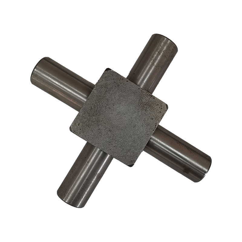
1. Variable speed universal joints.
When the angle between the two shafts connected by the universal joint is greater than zero, the output shaft and the input shaft transmit motion at a variable instantaneous angular velocity ratio, but the average angular velocity is the same.
The cross-shaft rigid universal joint is composed of universal joint fork, cross shaft, needle bearing, oil seal, sleeve, bearing cover and other parts. The working principle is: one of the rotating forks drives the other fork to rotate through the cross shaft, and at the same time, it can swing in any direction around the center of the cross shaft. The needle in the needle roller bearing can rotate on its own during rotation to reduce friction. The shaft connected with the input power is called the input shaft (also called the driving shaft), and the shaft output through the universal joint is called the output shaft (also called the driven shaft). Working under the condition of an included angle between the input and output shafts, the angular speeds of the two shafts are not equal, which will cause the output shaft and the transmission components connected to it to produce torsional vibration and affect the life of these components.
2. Quasi-constant velocity universal joint.
Refers to a universal joint that transmits motion at an equal instantaneous angular velocity under a design angle, and transmits motion at an approximately equal instantaneous angular velocity under other angles. It is divided into: a) Double quasi-constant velocity universal joint. Refers to the universal joint when the length of the transmission shaft in the universal joint constant velocity transmission device is shortened to the minimum. b) Bump type quasi-constant velocity universal joint. It is composed of two universal joints and two bumps of different shapes. The two protrusions are equivalent to the intermediate drive shaft and two cross pins in the double universal joint device. c) Three-pin shaft quasi-constant velocity universal joint. It consists of two three-pin shafts, an active eccentric shaft fork and a driven eccentric shaft fork. d) Spherical roller type quasi constant velocity universal joint. It is composed of pin shaft, spherical roller, universal joint shaft and cylinder. The roller can move axially in the groove to play the role of telescopic spline. The roller contact with the groove wall can transmit torque.
3. Constant velocity universal joint
A universal joint in which the output shaft and input shaft connected to the universal joint transmit motion at the same instantaneous angular velocity at all times. It is divided into:
a) Ball and fork type constant velocity universal joint. A universal joint composed of a ball fork with a raceway and a steel ball. Among them, the arc groove raceway ball fork universal joint refers to a universal joint in which the ball raceway on the sphere is an arc type. The joint structure is characterized by arc grooves made on the driving fork and the driven fork of the ball fork. After the two are assembled, four steel ball raceways are formed, and a total of 4 steel balls are accommodated in the raceways. The centering steel ball is installed in the spherical groove in the center of the main and driven forks. Straight groove raceway ball fork universal joint refers to a universal joint with a straight groove raceway on the ball fork. Its structural feature is that straight grooves are made on the two ball forks, and each straight groove is inclined to the center line of the shaft, and the inclination angle is the same and symmetrical to each other. There are 4 steel balls in the raceway between the two ball forks.
b) Ball cage type constant velocity universal joint. According to whether the universal joint can move in the axial direction, it can be divided into an axially non-telescopic (fixed) ball type universal joint and a retractable ball type universal joint. Structurally, the inner surface of the star sleeve of the fixed ball cage universal joint is connected with the drive shaft with inner splines, and its outer surface is made with 6 arc-shaped grooves as the inner raceway of the steel ball, and the outer raceway is made in On the inner surface of the spherical shell. The six raceways formed by the star sleeve and the spherical shell are each equipped with a steel ball, and the cage (ball cage) makes the six steel balls in the same plane. The power is transmitted from the drive shaft through the steel ball and spherical shell (Figure 2). The structural feature of the telescopic ball cage universal joint is that cylindrical straight grooves are made on the inner wall of the cylindrical shell and the outer part of the star sleeve, and steel balls are installed in the raceway formed by the two assembled. The steel ball is also installed in the hole of the cage. The inner hole of the star sleeve is splined to connect with the input shaft. This structure allows the star sleeve and the simple shell to move in the axial direction relative to each other.
 English
 简体中文
简体中文 русский